Overview of Two‑Post Lifts
Two-post lifts save space, provide clearance for maintenance, and make repairs quicker and more convenient. They have become popular with DIY enthusiasts for home garage use. Install on a level concrete floor, anchor securely, and connect a 220V supply for the hydraulic pump. Ensure proper function.
What Is a Two‑Post Lift?
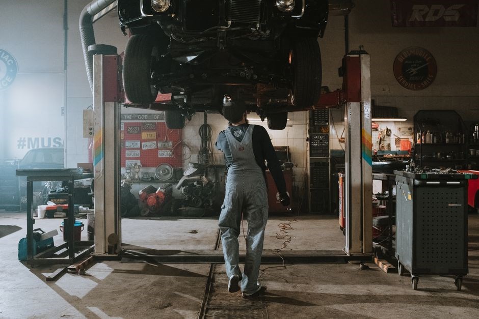
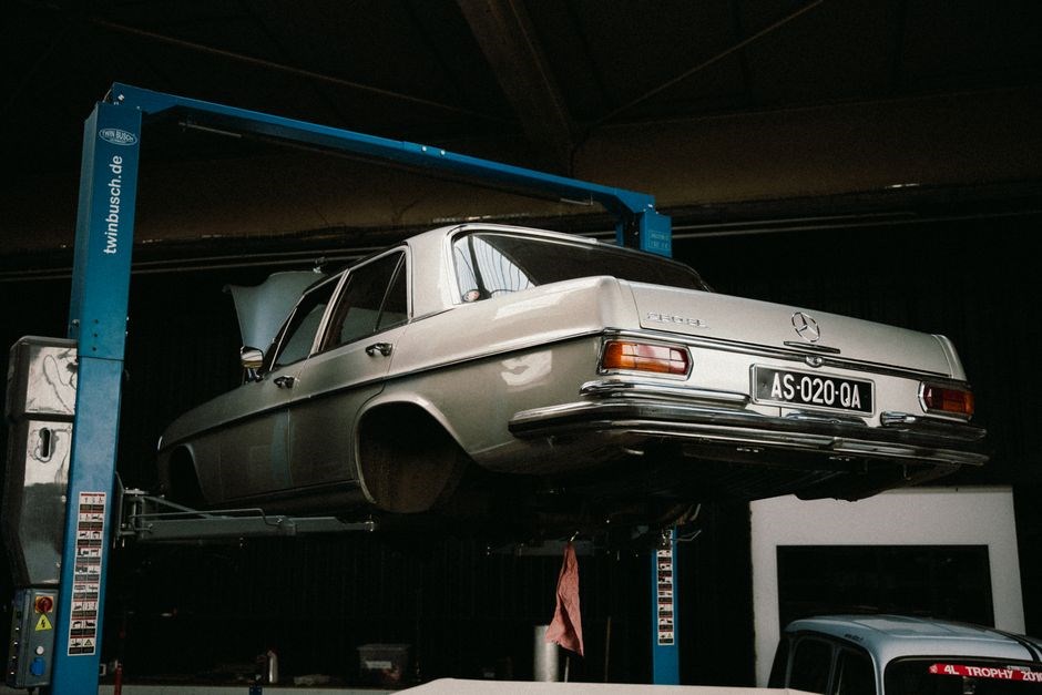
A two-post lift is a vehicle lifting device consisting of two vertical columns, each housing a hydraulic cylinder or screw drive mechanism, connected at the top by a crossbeam or overhead beam. The columns feature adjustable swing arms that engage designated lifting points on the vehicle frame or chassis. Unlike four-post runway lifts, this design provides unobstructed access to wheels, brakes, and suspension components for service work. They are categorized primarily as symmetric or asymmetric based on arm geometry and column placement relative to the vehicle center of gravity. Symmetric lifts position the vehicle centered between columns with equal arm lengths, ideal for trucks and vans. Asymmetric lifts rotate columns approximately 30 degrees and use shorter front arms, allowing doors to open wider on passenger cars. Capacity typically ranges from 7,000 to 18,000 pounds. Key components include the power unit (electric motor and hydraulic pump), hydraulic hoses, equalization cables or chains for synchronization, mechanical safety locks (latch systems), and rubber lifting pads. Professional installation requires a reinforced concrete slab of specific thickness (usually 4 inches minimum at 3000 PSI) and heavy-duty anchor bolts. Overhead and baseplate styles differ significantly in beam placement; overhead needs ceiling height, baseplate needs floor space. Arms typically telescope three stages with rubber pads for wheelbases. Controls vary from simple pendant stations to wireless remote units. Arm restraints prevent shift. Understanding these fundamentals is critically essential before planning a home garage installation project successfully now.
Advantages Over Other Lift Types
Two‑post lifts offer a compact footprint that fits comfortably in most residential garages, freeing valuable floor space compared with four‑post or in‑ground runway systems. Their open‑frame design provides unobstructed access to wheels, brakes, suspension and under‑body components, allowing mechanics to work on both sides of the vehicle without removing the lift. Because the lift raises the vehicle by the wheels rather than the chassis, clearance beneath the car is maximized, making tire changes, exhaust repairs and fluid servicing faster and safer. The hydraulic or screw‑drive mechanisms deliver smooth, precise lifting and lowering, which reduces the risk of sudden drops that can damage sensitive components. Many models incorporate safety latches and equalizer bars that automatically balance load distribution, enhancing stability on uneven floors. Compared with scissor lifts, two‑post units typically have higher load capacities—ranging from 7,000 to 18,000 pounds—while remaining lighter and easier to relocate. Their relatively low purchase price and straightforward assembly have attracted DIY enthusiasts, who appreciate the ability to install the lift themselves with basic tools and a concrete slab. Overall, the blend of space efficiency, superior access, higher capacity, safety features and affordability makes two‑post lifts the preferred choice for home garage owners seeking professional performance without the complexity of larger commercial systems. Adds resale value.
Typical Applications in Home Garages
Homeowners typically install two‑post lifts to handle routine maintenance like oil changes, brake service, tire rotations, and suspension repairs without the discomfort of working on a cold concrete floor. The open architecture grants unobstructed access to the entire undercarriage, simplifying exhaust replacement, transmission fluid flushes, differential servicing, and steering component inspections. Classic car restorers rely on the lift to secure chassis at ergonomic heights for bodywork, welding, rust repair, and paint preparation over extended periods. Weekend racers value rapid wheel changes and precise corner‑weight adjustments before track events. The unit doubles as a storage multiplier, allowing a second vehicle to park beneath the raised platform, effectively maximizing limited garage square footage. Fabricators appreciate the stable, elevated platform for building custom exhaust systems, driveshafts, and roll cages while standing upright, which reduces fatigue and improves weld quality. Detailers rotate vehicles easily to reach roof panels, rocker panels, and lower body lines for thorough cleaning and ceramic coating application. With rated capacities between 7,000 and 12,000 pounds, these lifts accommodate daily drivers, heavy‑duty trucks, and SUVs alike. A properly anchored installation on a reinforced four‑inch slab ensures absolute stability during every task, transforming a residential garage into a professional‑grade workshop. This versatility makes the two‑post lift an indispensable centerpiece for serious automotive enthusiasts demanding professional results at home every day with confidence now and maximum efficiency today now.
Pre‑Installation Planning
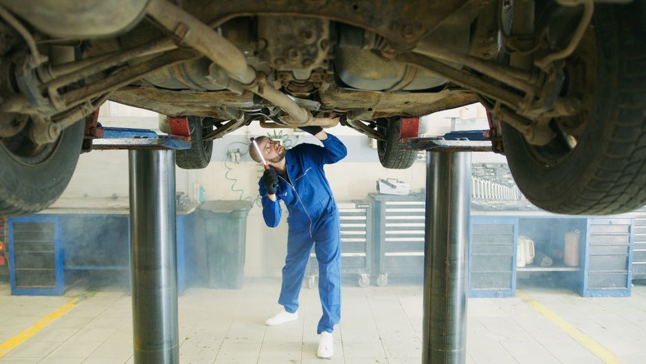
Verify ceiling height exceeds twelve feet for full rise. Ensure four‑inch reinforced concrete slab for anchor bolts. Arrange dedicated 220V single‑phase circuit. Obtain required permits. Clear area for column erection and hydraulic routing. Review manual thoroughly before starting work now. Check floor flatness.
Site Selection and Floor Requirements
Select a level area free of obstacles where the lift can be centered under the garage ceiling. The floor must be a solid, uncracked concrete slab; a minimum thickness of four inches with #4 rebar spaced 12 inches on center is recommended. If the existing slab is thinner, apply a two‑inch reinforced overlay before drilling anchor holes. Verify the slab’s compressive strength is at least 3,000 psi and calculate a safety margin of 25 % above the lift’s rated load, typically 4,500 lb for passenger vehicles. Anchor bolts of ½‑inch diameter are set in epoxy grout to a depth of six inches, following the manufacturer’s layout plan. Provide at least six feet of clearance on each side of the lift to allow safe vehicle entry and operator movement. Ceiling height must accommodate the lift’s full‑travel height plus the vehicle’s height and an additional twelve inches of headroom; measure this before installation. Avoid locations near heat sources, chemicals, or excessive moisture that could accelerate corrosion of steel components. Finally, consult local building codes, obtain any required permits, and document the floor‑rating calculations and anchor‑bolt pattern for inspection.Confirm that the anchor‑bolt pattern matches the manufacturer’s engineering drawing, spacing bolts no more than 24 inches apart, and use a torque wrench to tighten each bolt to the specified 150 Nm; record the torque values in a log for future reference.Ensure the slab is clean, dry and free of oil now.
Load Capacity Calculations
To determine the appropriate lift rating, begin by identifying the heaviest vehicle you intend to raise, including any added accessories such as batteries, fuel tanks, and aftermarket parts. Record the gross vehicle weight rating (GVWR) from the manufacturer’s specifications; for most passenger cars this value ranges between 3,000 lb and 4,500 lb, while light trucks and SUVs can exceed 6,000 lb. Add a 15% contingency to accommodate future upgrades or measurement tolerances, then apply a safety factor of 1.25 as required by most industry standards. For example, a 5,200 lb SUV with a 15% buffer becomes 5,980 lb; multiplied by 1.25 yields a required lift capacity of 7,475 lb, so a lift rated at 8,000 lb would be selected. Verify that the hydraulic cylinder’s pressure rating and the cross-beam’s moment capacity exceed this figure; manufacturers typically list a maximum load per column, and the combined rating must meet or surpass the calculated requirement. Next, confirm that the concrete slab can support the static load plus dynamic forces during lifting. The slab’s compressive strength, expressed in psi, should be at least 3,000 psi, and the anchor bolts must be sized to resist shear forces calculated as the lift load divided by the number of anchors, with a minimum bolt diameter of 1/2 in and a torque setting of 150 Nm. Finally, document all calculations in a load capacity worksheet, retain the certification sheet, and have installation inspected by professional before use.
Required Tools and Safety Gear
Prior to installation, verify the availability of every tool and protective item listed below to prevent interruptions. Heavy‑duty tools: rotary hammer drill with 3/4‑in and 1/2‑in carbide‑tipped bits for anchor holes, a calibrated 150 Nm torque wrench for anchor bolts, a 4‑ft machinist level and a laser plumb bob to achieve column plumb within 1/16 inch, adjustable wrenches up to 1‑1/2 in, a metric socket set including 19 mm and 24 mm deep impact sockets, a 3‑ton hydraulic floor jack for crossbeam positioning, a digital multimeter to confirm 220 V single‑phase power, chalk line, 25‑ft tape measure, permanent marker, shop vacuum with HEPA filter for silica dust, and a 24‑in pry bar for fine alignment. Consumables: wedge anchors (1/2‑in x 5‑1/2 in, grade 8), hydraulic fluid (ISO 32), and thread‑locking compound. Personal protective equipment (PPE) is non‑negotiable: ANSI Z87.1 rated safety glasses with side shields, cut‑resistant level A4 gloves, steel‑toe boots with metatarsal guards meeting ASTM F2413, Class G hard hat, hearing protection rated NRR 25 dB or higher, and flame‑resistant coveralls when handling hydraulic oil. A 10 lb ABC fire extinguisher must be mounted within 10 ft of the work area. Inspect all tools for wear; damaged bits or out‑of‑calibration wrenches compromise structural integrity and endanger personnel. Log each item on the pre‑installation checklist, sign off, and retain the record for certification audit. Additionally, confirm the concrete slab thickness meets the minimum four‑inch requirement and that the anchor embedment depth achieves the manufacturer’s specified pull‑out resistance value before tightening bolts to final torque. Ensure all docs are photographed and stored digitally.

Step‑by‑Step Installation Procedure
Follow the manual carefully. Begin by marking column positions, drilling anchor holes, and erecting uprights. Next, mount the crossbeam, route hoses, and wire the power unit. Finally, bleed the system, test lift cycles, and verify safety locks engage properly before use.
Assembling the Upright Columns
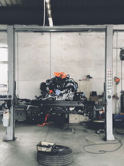
Begin by unpacking and inventorying every component against the manufacturer’s packing list, verifying no shipping damage occurred. Identify the power-side column containing the hydraulic cylinder and the idler-side column which houses the equalization cables. Lay both columns horizontally on protective cardboard or rubber mats near their final installation positions to prevent finish damage. Attach the base plates using supplied Grade-8 bolts, flat washers, and lock nuts, torqueing to the exact specification—typically 150 ft-lb for 3/4-inch anchors. Install the carriage assemblies onto each column before raising them; ensure rollers or slider blocks move freely within the track channels without binding. Insert safety latch mechanisms, verify spring tension, and engage pawls manually to confirm positive locking action. Route the hydraulic hose through the designated internal channel in the power column, securing it with provided clamps to prevent chafing during operation. With assistance or a forklift, carefully tilt the first column vertical. Align base plate holes precisely with pre-drilled floor anchor locations. Insert heavy-duty wedge anchors, leaving sufficient thread exposure for leveling nuts and hardened washers. Plumb the column using a magnetic level on both front and side faces; insert precision shims as required to achieve perfect verticality within 1/32 inch. Tighten anchor nuts to specified torque in a star pattern to distribute load evenly. Repeat the process for the second column, maintaining strict parallelism within 1/8 inch across the full height. Double-check column height alignment and carriage level before proceeding to crossbeam installation. Confirm concrete slab meets 3000 psi minimum and verify overhead clearance for full extension. Apply anti-seize compound to anchor threads for corrosion protection, then re-torque all anchors after first lift cycle.
Installing the Crossbeam and Hydraulic System
After the columns are plumbed and anchored, lay the pre‑drilled crossbeam on the floor between them, aligning the bolt‑hole pattern with each column flange. Insert the supplied M12 × 1.75 pins through the crossbeam and into the column brackets, then torque each bolt to 120 ft‑lb using a calibrated wrench and apply thread‑locking compound. Ensure bolts are tight.
Next, place the hydraulic pump on the power‑side column and bolt the base plate with four M10 anchors tightened to 90 ft‑lb. Mount the cylinder to the column brackets, then run the high‑pressure hose through the internal conduit, securing it with the supplied stainless‑steel clamps tightened to 25 in‑lb. Verify hose is free of kinks and fittings are snug now. OK
Connect the low‑pressure return line from the cylinder to the reservoir, following the flow‑direction arrows on each fitting. Fill the reservoir with the recommended ISO VG‑46 hydraulic fluid to the MAX mark. Operate the lift slowly by hand lever to purge air, watching the sight glass for bubbles. Verify lift reaches full height, then lowers smoothly, no leaksOK.
Finally, wire the pump motor to a dedicated 240 V circuit protected by a 20 A GFCI breaker. Use the supplied three‑wire cable and follow the wiring diagram, securing connections with torque‑rated nuts. Perform a load test by raising the lift with a 50 % rated weight to full height, observing for abnormal noise, vibration, or fluid leakage. Verify safety stickers.
Connecting Electrical and Testing the Lift
Install a dedicated 240 V circuit with a 20 A GFCI breaker. Shut off power before stripping a three‑conductor cable, then connect black and red wires to the pump’s L1/L2 terminals (torque 8 in‑lb) and green to ground (torque 12 in‑lb). Secure the cable with a rated clamp.
Mount the control panel on the nearest column using four M8 bolts (torque 8 in‑lb). Run the wiring through the pre‑drilled conduit, attach power leads, and wire “up”, “down” and emergency “stop” buttons as shown in the schematic. Verify polarity and grounding.
Restore power and perform a visual check: LEDs should light, the pump should hum without vibration, and the emergency stop must cut power instantly. Raise the empty lift with the “up” button; the crossbeam should reach full height in under 20 seconds, fluid level staying steady. Lower it with the “down” button, confirming smooth retraction and no leaks.
Conduct a load test with a ½‑rated vehicle chassis. Raise the lift, hold for 30 seconds, then lower. Verify that the lift holds position, the motor stays cool, and the control panel shows “ready”. Record results, sign the log, and affix the manufacturer’s certification tag.
Final verification includes checking that all fasteners remain tight after the first lift cycle, confirming that the grounding conductor shows no voltage drift, and ensuring the control panel label matches the model number. Keep a copy of the test log for future inspections. (recorded) now
Post‑Installation Checklist and Maintenance
After installation, verify anchor bolt torque, hydraulic fluid level, and electrical connections. Perform a no-load cycle, then a full-load test. Schedule monthly lubrication of columns, chain inspections, and annual professional certification to ensure safe operation and longevity. Check locks.
Initial Safety Inspection and Certification
Before using a newly installed two‑post lift, perform a complete safety inspection. Verify the lift is bolted to a level concrete slab and all anchor bolts are torqued to the manufacturer’s recommended value. Examine the upright columns for dents or corrosion, and check the cross‑beam for cracks. Ensure hydraulic cylinders are firmly attached, fluid is clean and at the proper level, and the pressure gauge reads within the specified range.
Inspect the electrical components. The power cord must be intact, the plug should match the lift’s voltage rating (typically 220 V), and a dedicated circuit breaker must protect the unit. Test the emergency stop and any safety interlocks; they must cut power immediately. Confirm that safety pins engage automatically when the platform is raised.
Conduct functional testing. Raise the lift without a vehicle, hold at full height for 30 seconds, then lower slowly, noting any abnormal noises. Repeat with a test load equal to the lift’s rated capacity (3,000–4,000 lb for most home models). After testing, record results on the certification form, sign it, and affix the label where it is clearly visible.
Maintain records and schedule periodic checks. Keep the lift’s manual accessible, log each inspection, fluid change, and part replacement. Verify that safety decals remain legible, and re‑calibrate the pressure gauge annually. Store the lift in a dry area to prevent rust.Inspect the hydraulic hoses quarter for wear or cracks.
Routine Maintenance Schedule
Regular upkeep keeps a two‑post lift safe and reliable. Follow the timetable below.
- Daily: Visual check for oil, levelness, and secure safety pins. Remove debris.
- Weekly: Test emergency stop, lubricate column pivots, spray hose fittings.
- Monthly: Inspect hydraulic fluid clarity, top up if needed, verify pressure gauge, tighten loose wires.
- Quarterly: Re‑torque anchor bolts, examine crossbeam for cracks, check cylinders for leaks, replace worn seals.
- Annual: Professional load test, calibrate gauge, certify lift, record results on log sheet.
In addition to the scheduled tasks, always keep the work area well‑ventilated and free of combustible materials. Store the hydraulic fluid in a sealed container away from direct sunlight, and label all hoses clearly. When performing any adjustment, disconnect power and depressurize the system to prevent accidental movement. Keep a copy of the manufacturer’s manual on hand for reference during maintenance.
Document each maintenance activity in a log, noting date, performed task, and any observations. This record helps track wear patterns and supports warranty claims should a component fail.
Check warranty terms annually to stay within req service intervals keep log today!!
Troubleshooting Common Issues
Even with careful installation, problems can arise. Below are frequent faults, causes, and fixes to restore function quickly.
- Lift will not rise: Verify 220V supply, reset tripped breaker, confirm hydraulic fluid level is at max mark, inspect pump motor for burnout, check pressure relief valve for debris.
- Uneven lifting: Bleed trapped air from both cylinders using bleed screws, ensure concrete floor is perfectly level, check synchronization cables or chains for equal tension and wear.
- Hydraulic fluid leaks: Tighten all JIC and ORB fittings to spec, replace cracked hoses or worn piston seals immediately, clean area thoroughly to pinpoint exact leak origin.
- Excessive noise or vibration: Lubricate carriage slide blocks and sheave bearings, inspect for worn polyurethane pads, verify pump cavitation caused by low fluid or clogged suction filter.
- Safety locks fail to engage: Remove debris from latch teeth, adjust latch bar alignment with column slots, test lock solenoid voltage and replace faulty coil.
- Slow or jerky operation: Replace clogged return filter, adjust relief valve pressure to factory setting, inspect electric motor brushes for wear, check voltage drop;
Always disconnect power and depressurize system before any repair. Consult the manufacturer manual for torque specifications, schematics, and adjustment procedures. If problems persist after these steps, contact a certified lift technician immediately to prevent injury or damage. Document repairs in the maintenance log for warranty tracking and diagnostics. Additional troubleshooting resources include manufacturer bulletins, online forums, and certified training courses for advanced diagnostics. Keep detailed records of interventions for future reference and liability protection!!